
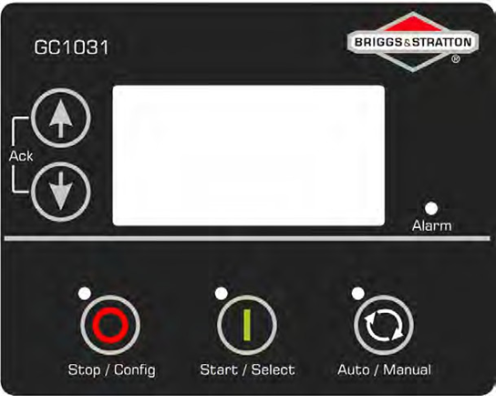
The GC1031 Genset Controller is designed to manage the operations of 1-phase and 3-phase gensets efficiently. It integrates seamlessly with electronic governor controllers and offers a variety of operational modes including Auto, Manual, and Remote Start/Stop. Its backlit and full graphics display includes a power-saving feature, enhancing the user interface and experience.
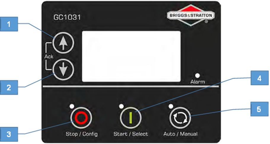
- Menu Navigation Up key
- Menu Navigation Down key
- Stop/Config key
- Start/Select key
- Auto/Manual Mode selection key
Key Features
- Multiple Operational Modes: Includes Auto Mode, Manual Mode, and Remote Start/Stop, catering to different operational needs.
- RPM Sensing: Utilizes frequency and MPU for accurate RPM sensing.
- Auto Exercise Modes: Supports automatic exercise modes for routine checks and maintenance.
- Connectivity: Offers various connectivity options including USB, RS485, and CAN J1939 for comprehensive monitoring and control.
- User Interface: Features a backlit and full graphics display with a power-saving feature for enhanced visibility and energy efficiency.
Installation and Safety
The manual provides detailed instructions on the installation process, ensuring safety and efficiency. It emphasizes the importance of adhering to safety warnings to prevent personal injury and equipment damage. The safety symbols and definitions guide users through potential hazards and necessary precautions.
Configuration and Customization
The GC1031 allows extensive customization through a wide range of configurable parameters. Users can enter configuration mode to adjust settings like power mode, language, communication settings, and various thresholds and alarms. The manual provides a step-by-step guide on navigating and setting these parameters, ensuring the controller operates according to specific needs.
Troubleshooting and Maintenance
For operational efficiency and longevity, the manual includes a troubleshooting section detailing common faults and remedial actions. It also outlines maintenance procedures to ensure the genset controller remains in optimal condition.
| Sr. No. | Faults | Remedial Actions |
| Possible Issues in MANUAL Mode | ||
| 1 | The controller does not power ON. | Check the battery voltage.Check the fuse on the battery supply.Check continuity between battery positive and controller terminal # 2.Check continuity between battery negative and controller terminal # 1. |
| 2 | The controller fails to crank-start the engine. | Check the battery voltage.Enter “Configuration Mode” in controller and verify the configuration for the “START” output. Also, check that “START” output is working correctly by measuring its output voltage.Enter “Configuration Mode” in controller and verify the configuration of “CRANK DISCONNECT” method. |
| 3 | The “Emergency Stop” alarm comes up even when the “Emergency Stop” is not pressed. | Check if the “Emergency Stop” switch is working OK. Check its wiring also.Enter “Configuration Mode” in controller and verify the configuration of “EMERGENCY STOP” polarity. |
| 4 | The controller generates unnecessary “Shutdown Alarms” or “Warning Alarms” | Check the respective switch/sensor and wiring.Enter “Configuration Mode” in the controller and verify the respective threshold configuration. |
| 5 | The engine runs, but the controller shows genset to be “OFF”. | Check if the MPU signal (if used), and main alternator voltage signal (R/L1 phase) are received by the controller terminals.Check if the LOP and LLOP are working OK. Also check their wiring to the controller. |
| 6 | The controller displays incorrect PF value or kW or load current. | Check wiring of the respective alternator phase voltage and the CT to the controller.Check the CT ratio (if kW or current reading is faulty). |
| 7 | The controller displays incorrect Mains voltage or incorrect main alternator voltage. | Check the wiring of the respective phase to the controller. |
| 8 | Controller displays incorrect reading for any of LOP, Fuel Level, Temperature sensors. | Check respective sensor and its wiring.Enter “configuration mode” in the controller and verify the calibration for the respective sensor in configuration. |
| 9 | The controller displays incorrect engine RPM. | Check the MPU connection and configuration (if enabled).Check wiring of the main alternator’s R-phase and neutral to the controller. |
| Possible Issues in AUTO Mode | ||
| 10 | The controller does not start the engine even when a “Remote Start” command is sent from an external device such as a telecom PIU. | Check the wiring of the “Remote Start” signal to the controller’s respective digital input terminal.Enter “Configuration Mode” in the controller and verify the configuration for the “Remote Start” digital input terminal.Check that the controller is in “Auto Mode. ”For 2 wire start verify “MAINS MONITORING” is disabled |
| 11 | Controller does not stop engine even when a “Remote Stop” command is sent from an external device such as a telecom PIU. | Check the wiring of the “Remote Stop” signal to the controller’s respective digital input terminal.Enter “Configuration Mode” in the controller and verify the configuration for the “Remote Stop” digital input terminal.Check that the controller is in “Auto Mode. ” |
| 12 | While in Auto Mode, controller issues “Start” command even if the Mains present. | Check the wiring of the Mains R, Y and B phase to the controller’s respective input terminal.Enter “Configuration Mode” in the controller and verify the configuration for the “MAINS MONITORING”. |
| Possible Issues with Electronic Governing | ||
| 13 | The controller does not maintain the target RPM. The engine RPM is not stable or engine hunts. The controller cranks the engine but does not start the engine. | Check the wiring of the actuator to the controller’s terminal. Check if the mechanical linkage assembly is OK. Enter “Configuration Mode” in the controller and verify the configuration for “GOVERNOR”. Also, check the PID control gains. Check that the Actuator moves to full throttle position when the engine is cranked. |
Conclusion
The GC1031 Genset Controller is a versatile and user-friendly device designed to enhance the operation and management of gensets. With its comprehensive features and customizable settings, it ensures reliable and efficient genset performance. The manual is an essential resource, providing detailed instructions and safety information for users.
For more detailed information, users are encouraged to refer to the full operator’s manual.
Disclaimer: Due to continuous development, the details provided in this document are subject to change without any prior notice.